Find Content
Field Aging Behavior of Long Rods Analyzed According to Cigré TB 306
Laboratory analysis of sub-critical crack growth in ceramic bodies induced by routine thermal cycling

Key Takeaways
Abstract
The remaining lifetime of the aging grid is an important global issue; the Transmission Systems Operators (TSOs) must predict end-of-life and refurbish at the right moments, not too early and not too late.
Cigré guide TB 306 (1) is one of the tools widely used to conduct risk assessment for the aging of glass and ceramic insulators. TB 306 is based on statistical analysis of a population of aged insulators. A selected batch is divided into two groups. The 1st is tensile tested as arrived, and the 2nd group undergoes a Thermo-Mechanical Performance (TMP) test according to IEC 60383 before being broken afterwards.
The purpose of the TMP is to provoke crack growth on microcracks nucleated in service and create accelerated aging to estimate the remaining lifetime. In practice, the TMP is often replaced by a routine thermal cycling test, as the laboratory TMP-test capacity is limited.
The intention of this study was to analyze in the laboratory how the routine thermal cycling test creates a sub-critical crack growth on the ceramic body.
Two different ceramic recipes for C-120 and C-130 porcelains were evaluated with calibrated defects. Their mechanical strength was measured, and their microstructure was analyzed. It was not possible to create confirmed crack growth on the samples, but the importance of the alumina content and the mineralogical structure to the mechanical performance was clearly proved.
The best way to improve the crack growth resistance on the Long Rods was discussed, as field data suggests that insulators with higher alumina and optimized corundum/mullite ratio do not show field aging.
Introduction
Electric energy supply security and availability are strategic topics for all Transmission Systems Operators (TSOs): our society tolerates fewer and fewer blackouts, and the potential consequences are increasingly serious and expensive.
The risk of energy supply disruption is constantly evaluated, and actions are taken to mitigate the risk, build systematic redundancy to the grid, and prepare quick recovery plans to limit the damage.
The blackout risks that are present in the media and publicly debated are mostly related to storms, voltage surges caused by cascading grid disconnections, hybrid warfare, and other unforeseen reasons.
However, there is another creeping risk factor which is less discussed publicly: aging.
This is a known risk to the TSO’s, but it receives less public attention. Aging is extremely difficult to quantify, as multiple factors have an impact: insulator and installation design, external service conditions, material choice and operations.
Those who are familiar with reliability engineering know that aging follows the bathtub curb. When the end-of-life approaches and the individual failures start to increase exponentially, it is already too late to react. On the other hand, refurbishing installations and transmission lines earlier is more economically sustainable.
TB 306 focuses on mechanical aging and the statistical probability of failures. The collected samples of insulators are divided into two groups, where the 1st group of insulators is mechanically tested as arrived, and the 2nd group is artificially aged by Thermo-Mechanical Performance Test (TMP), then the results are plotted in a probability diagram as we can see on Graph 1.
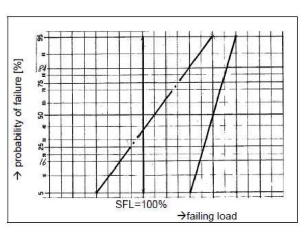
Graph 1: Scenario F3 from Cigré TB 306(1), where the solid line presents failing as arrived and the dashed/dotted line after the TMP testing. Source: PPC Insulators.
We can see how the artificial aging has moved the failing load on the left and it is crossing the Specific Failing Load at 35 % probability. This shows advanced aging even when the insulators were tested as received. In such cases, the recommendation would be to repeat the test in a couple of years to see if the insulators have further deteriorated.
In practice, when thousands of kilometres of overhead lines and hundreds of ceramic long rods must be evaluated, TMP is unsuitable due to long cycle times.
TMP testing requires 96 hours per insulator, and on the test device, there is room for only a single, eventually two, Long Rods.
This is why TSOs often replace TMP with a temperature cycle test according to IEC 60383 § 24.1, which takes about 3 hours for class A insulators (Long Rods), and 6 Long Rods can be tested at one time. In one working week, 60 Long Rods can be thermally cycled compared to one single TMP-tested insulator. (2)
The 70 K thermal shock test is a routine test used to eliminate pieces with potentially internal stresses or other material inhomogeneities, such as pores, microcracks, residual quartz, and foreign particles.
Thermal shock can cause open cracks during testing or initiate crack propagation, thereby reducing the mechanical strength in subsequent tensile testing.
What is then unknown is how the thermal shock might affect the crack propagation and simulate accelerated aging.
In this study, we have tried to quantify on a laboratory scale how the thermal shock causes crack propagation on a small ceramic laboratory bar with a calibrated material defect.
The sample preparation and experimental method
The goal of this experiment was to prepare “calibrated defects” in the test bar to study their impact on crack propagation in laboratory conditions.
Manufacturing “calibrated defects” is a classical Root Cause Analysis (RCA) method used in modern Quality Management.
Based on the results from a quartz impact study from 2022 (3), where the 64 µm quartz sand particles were used to contaminate the base body, the same method was selected to create non-homogeneities in the body.
The 64 μm fraction was sieved and selected because this fraction is close to A. Rawat and R. S. Gorur’s findings: aged insulator samples with > 50 μm quartz failed on the punctuation test (4).
In the 2022 quartz study (3), it was shown that 1% of this fraction of quartz particles reduced the mechanical strength of C-130 porcelain by about 5-6%.
Two types of porcelain bodies were selected as base materials: A) a recipe for an isostatic production, C-130 with high alumina content, and B) a method and a C-120 recipe for a plastic manufacturing process.
1% wt. of quartz particles was mixed into the base body in the laboratory mill. For baseline test bars with 0% wt., the quartz was made of the same batch of body.
The body was pressed in the laboratory, as can be seen in Fig. 1, and extruded with the laboratory extruder (Fig. 2) to 10 mm diameter and 150 mm long test-bars.
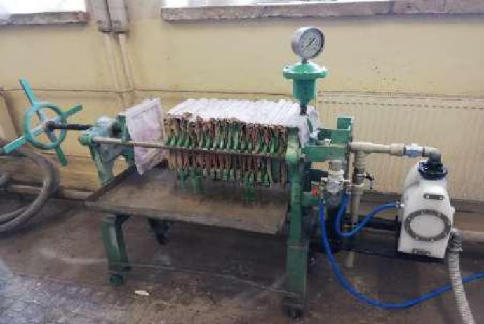
Fig. 1: The laboratory filter-press. Source: PPC Insulators.
Fig 2. The laboratory extruder. Source: PPC Insulators.
It was decided to make the test bars non-glazed. The glaze increases the mechanical strength of the body up to 30%, and that could potentially hide small crack propagation, which we were looking for.
After extrusion, the test bars were fired in the production kiln, as can be seen in Fig. 3.
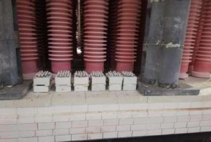
Fig 3. Samples ready on kiln for firing. Source: PPC Insulators.
The fired samples underwent thermal shock test according to IEC 60672 § 11, Method A (5). 10 samples were heated in the oven at 120 °C +/- 5 °C, over 2 hours, and quickly immersed in 20 °C water for 5 minutes. (Fig. 4).
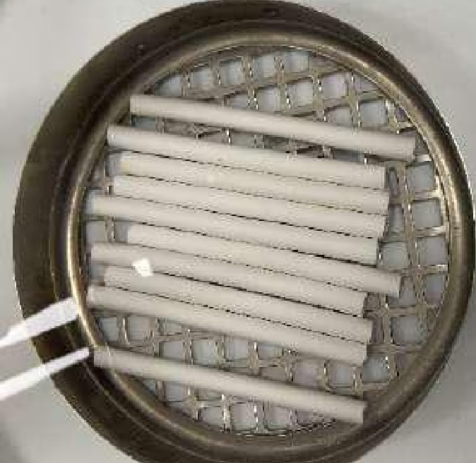
Fig. 4. Test bars immersed in 20°C water.
The thermal shock was repeated 3, 10, and 30 times on a batch of 10 samples. The standard defines only 3 shocks, but as it was uncertain if 3 cycles were enough to create crack propagation, which would be visible on the 3- point bending test, the 10 cycles and 30 cycles were added to the Experiment Design.
The 3 point-bending machine (Fig. 5) was used to break the test bars.
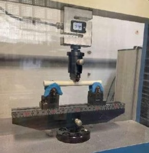
Fig. 5: The 3 point-bending machine. Source: PPC Insulators.
After the breakage of the sample, the breakage surfaces were inspected to ensure that the values were not affected by any material defect or impurity on the body.
Results
The 3-point bending results, averaged over 10 test bars, are presented in Tables 1 and 2.
| Table 1: Breakeage Value MPa | ||
| Body A | No Quartz | 1 % Quartz |
| Baseline | 188 | 165 |
| 3 cycles | 184 | 156 |
| 10 cycles | 181 | 161 |
| 30 cycles | 191 | 157 |
| Table 2: Breakeage Value MPa | ||
| Body B | No Quartz | 1 % Quartz |
| Baseline | 125 | 121 |
| 3 cycles | Fail | Fail |
| 10 cycles | 126 | 121 |
| 30 cycles | 121 | 116 |
Tables 1 and 2: 3-point bending results. Source: PPC Insulators.
The chemical analysis gave the following results, as seen on Table 3.
| Element | Body A | Body B |
| SiO2 | 39.0 % | 45.5 % |
| Al2O3 | 55.3 % | 47.5 % |
| Remaining | 5.7 % | 7.0 % |
Table 3: Chemical analysis results. Source: PPC Insulators.
The remaining oxides are typically iron oxide Fe2O3, titan oxide TiO2, calcium oxide CaO, magnesium oxide MgO, kalium oxide K2O and sodium oxide Na2O.
IEC 60672(5) does not specify the chemical analysis or minimum aluminum content. Anyhow, the alumina content is typical for C-120 and C-130 ceramic insulators manufactured today.
The mineralogical analysis results are presented in Table 4 below.
| Microstructure (%) | Body A No Quartz | Body A with Quartz | Body B No Quartz | Body B with Quartz |
| Cristobalite | 0,1 | 0,2 | 0,2 | 0,2 |
| Quartz | 1,0 | 1,0 | 2,6 | 2,5 |
| Corundum | 32,1 | 30,8 | 22,2 | 18,3 |
| Mullite | 19,4 | 19,5 | 8,7 | 7,4 |
Table 4: Mineralogical analysis
It should be noted that the accuracy of the XDR analysis is at its best 0.5 % when analyzing mineralogy structures, so values below 1 % are basically showing only a residual.
Discussion
The results are plotted on the graphs below.
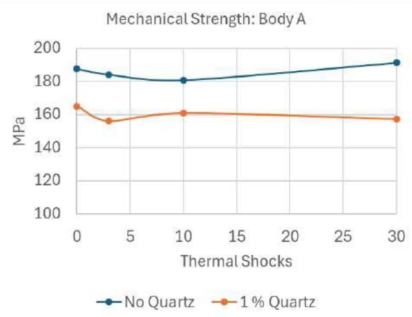
Graph 2: The change of 3-point breakage value of body A in function of thermal shocks. Source: PPC Insulators.
The first observation was that the 1 % quartz as an added impurity decreased the mechanical strength of body A by 14 %.
The loss of strength is more important than it was in the 2022 study (3), but it confirms the conclusion that the strength reduction is related to the quartz particle size, not quantity.
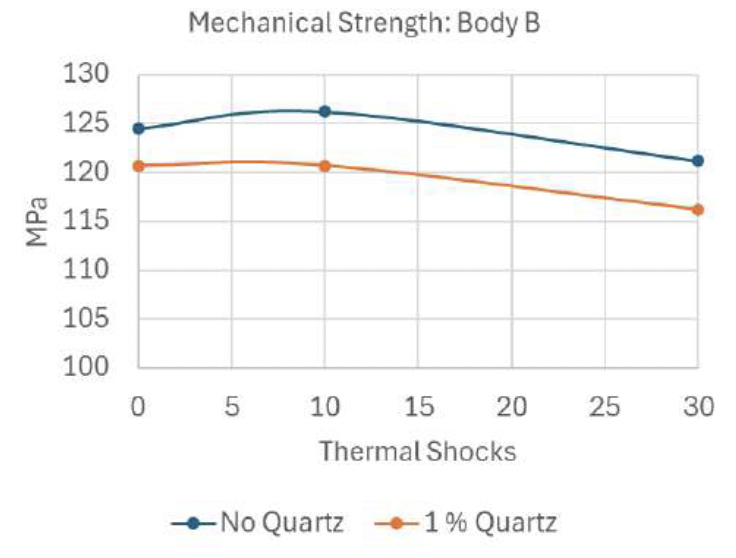
Graph 3: The change of the 3-point breakage value of body B in function of thermal shocks.
With body B, we observe a smaller loss of mechanical strength with added quartz particles, at just 4 %. The 3 thermal shock tests failed, but the 10 and 30 shock tests confirm the same observation as with body A.
We can see that the strength of body B is 35 % lower than that of body A. This can be explained by the chemical analysis and microstructure. It is well known that mechanical strength is related to alumina content, and body A has 8% more alumina (6,7).
Further to this, Liebermann (6,7) proposed that optimized C-130 has a phase relation of corundum > 40 %, mullit < 15 %, quartz < 1%, and the rest glass phase. The body A does not have an optimized structure, but it is close enough to give excellent results.
It can be assumed that the difference in the loss of strength of body A between the 2022 tests and this study comes from variations in the production firing curve.
The Quartz has a melting point of + 1713°C, but in the firing, the fluxes in the body, feldspar, and alkali oxides melt at around 1000°C – 1100°C, forming a liquid glassy phase, which can partially dissolve the quartz.
The degree of dissolution depends on the firing temperature, time and particle size. When the particle size is constant, the quantity and size of residual quartz particles are therefore dependent on the firing cycle variations in sample preparation.
The low level of residual quartz, whether or not a 1% fraction was added, also comes from this mechanism. Quartz particles are present in raw materials such as feldspar, kaolin, and clay, but their particle size is too small to affect strength. The impact on strength is due to the 64 μm.
The breakage surface was inspected by an electron microscope in the Department of Materials and Ceramic Engineering at the University of Aveiro in Portugal. The breakage surface molecules were analyzed by Energy‐Dispersive Spectrometry (ESD).
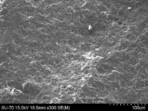
Fig. 6: Breakage surfaces of Body A, no added quartz, and no thermal shocks. Source: PPC Insulators.
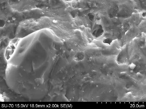
Fig. 7: Breakage surface of Body A, no added quartz, detail, where a small 20 µm x 30 µm quartz crystal is visible. No visible micro-cracks on surface. Small 1 – 2 µm pores in the ceramic. Source: PPC Insulators.
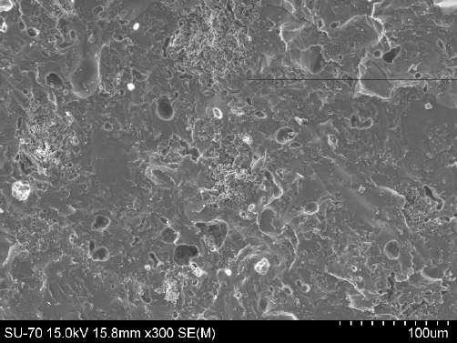
Fig. 8: Breakage surface of Body B, no added quartz, and no thermal shocks. Source: PPC Insulators.
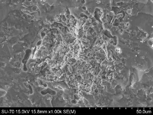
Fig. 9: Breakage surface of Body B, no added quartz, and no thermal shocks. Detail: of an alumina crystal cluster, confirmed by ESD. Source: PPC Insulators.
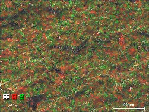
Fig. 10: Breakage surface of Body A, ESD analysis. Source: PPC Insulators.
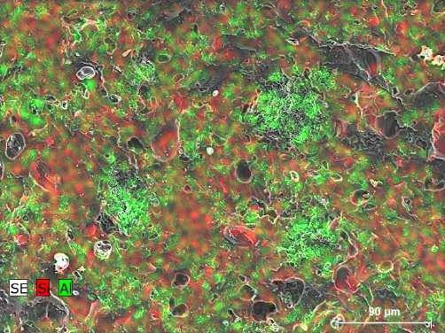
Fig. 11: Breakage surface of Body B, ESD analysis. Source: PPC Insulators.
The ESD reveals another main difference between bodies A and B. The alumina (green color) is homogeneously dispersed on body A. On body B, the alumina crystals have a tendency to be agglomerated.
This difference comes from the body preparation process and recipe. Body A is a recipe for Isostatic process and body B is a recipe for traditional plastic process. The microporosity is also bigger on body B, as the plastic body has a lower density after firing.
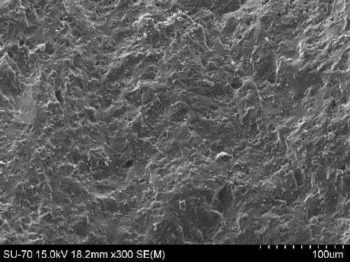
Fig. 12: Breakage surface of Body A added quartz and 30 thermal shocks. Source: PPC Insulators.
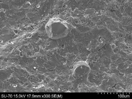
Fig. 13: Breakage surface of Body B added quartz and 30 thermal shocks. Source: PPC Insulators.
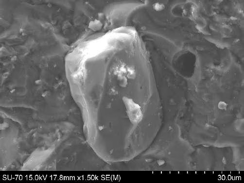
Fig. 14: Breakage surface of Body B added quartz and 30 thermal shocks. Detail: there seems to be a micro- crack on a 3 µm from the Quartz particle. Source: PPC Insulators.
The thermal shocks did not affect the mechanical strength, even when the first cracks around the quartz particles were observed on body B . This suggests that 30 cycles were not enough, causing further crack propagation. The 10mm test bar diameter is probably too small to cause a big enough temperature gradient, causing stresses for the sub-crack growth. The center and surface achieve the same temperature very quickly, almost at the same time.
When full-size insulators are cycled in the same way, the geometry makes a major difference: the sheds cool faster than the body. This will create greater thermal stress in the body with high thermal inertia than we can ever have with a 10mm test bar. In routine thermal cycling, the test insulator’s breaking point is systematically between the shed and the core.
The joint LAPP Insulators and 50-Hertz Long Rod Aging Study in 2023(2) showed that insulators manufactured 33 years ago didn’t show any aging. In cases where a material defect was observed in the ceramic breakage surface, the 3 thermal shocks according to IEC 60383-1 caused a small loss of strength, which was statistically insignificant, and was within the standard deviation of the examined batch of Long Rods. All tested insulators were significantly above the Specified Failing Load.
On other, non-disclosed, old-insulator analysis according to Cigré TB 306, it has become increasingly clear that the porcelain Long Rods were manufactured in the early 90’s. These insulators have high alumina content, and corundum is the dominating alumina crystal structure against the mullite. Both factors are an efficient way to reduce sub-critical crack growth.
Studies (7,9,10,11) comparing porcelains, glass-ceramics, and alumina-rich composites suggest that raising the alumina fraction usually:
- Increases fracture toughness (KIc) and strength.
- Raises the threshold stress intensity (K_I0) below which sub-critical propagation is negligible.
- Lowers the stress-corrosion susceptibility coefficient.
Multiple reviews and experimental papers (3, 4, 6, 9, 12) emphasize that the following elements influence sub-critical crack growth as much as nominal alumina percent:
- Alumina grain size
- Porosity
- Residual stresses
- The distribution/size of the glassy phase
- Residual quartz, grain size and distribution
- Corundum/mullite ratio
So, a limited quantity of large residual quartz grains; fine, well-bonded corundum grains plus limited, well-distributed mullite and low glass fraction give the best slow-crack resistance.
The microscopic and chemical analysis of bodies A and B confirms that statement. Body A had high alumina content, small particle size, a good corundum-to-mullite ratio with homogeneous distribution, and lower microporosity, which resulted in 35% higher mechanical strength, which is essential for reducing sub-critical crack growth.
Conclusions
In this study, it became clear that using laboratory test bars to simulate the impact of thermal shocks on sub-critical crack growth on the C-130 ceramic body is not efficient with 64 µm quartz particles.
In full insulator scale, the thermal mass of the core and fast cooling of the sheds create high enough stresses at thermal shock to create crack propagation when the existing non-homogeneity is big enough.
The field data and recent old-Long Rod assessments according to Cigré TB 306 suggest that routine thermal cycling according to IEC 60383-1 is enough to create sub-critical crack growth if the original material defects are big enough.
Analyzing Long Rods manufactured after the 90’s gives opposing results to what Freese and Pohlman suggested for lifetime assessment in 1999 (13). In cases where the ceramic body had a high alumina content and an optimized corundum/mullite ratio, their mechanical strength was equivalent to that of new ones after 35 years in service.
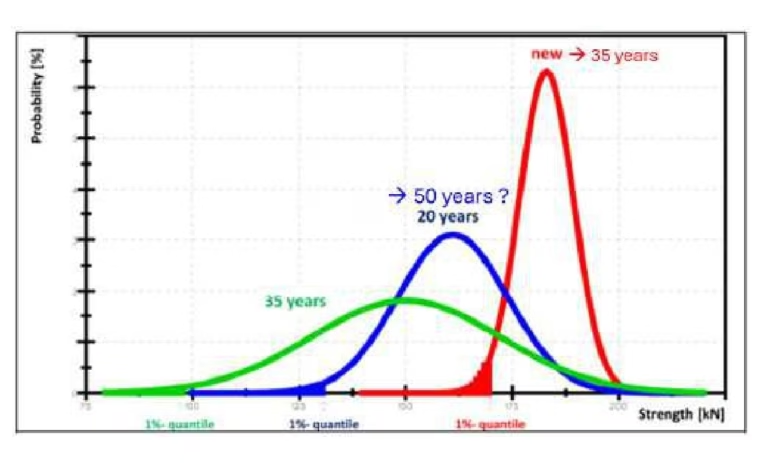
Graph 4: Statistical Long Rod life-time assessment by Freese and Pohlman suggested new levels. Source: PPC Insulators.
As there is a major structural difference between insulators manufactured before and after the 90’s, and between the manufacturers, the Cigré TB 306 assessment should always be completed with a failure and mineralogical analysis.
IEC 60672-3:1997 doesn’t specify anything about the alumina content or the microstructure of the C-120 or C-130.
C-120 is specified as:
“Feldspar fluxed porcelain in which quartz is partially replaced by alumina.”
And C-130 is specified as:
“Non-refractory, feldspar fluxed porcelain in which alumina is the principal filler.”
Perhaps it is time to revise IEC 60672-3:1997 and specify these two critical characteristics for the insulator’s lifetime: alumina content and microstructure.
References
[1] Cigré TB 306: “Guide for the assessment of old cap & pin and long-rod transmission line insulators made of porcelain or glass.” C. de Tourreil, B Staub, V. Sklenicka, Paris 2006
[2] “Aging Behaviour and Resistance of Ceramic Insulator,” INMR World Congress 2023 Bangkok. Markku Ruokanen ITG Group Quality and R&D Director; Erik Lehmann, Lineare Assets, 50Hertz Transmission GmbH
[3] “Impact of the residual quartz to the expected lifetime of C-130 alumina porcelain high voltage insulator”. Cigré Sessions 2022, Paris Paper 685. Markku RUOKANEN PPC Insulators Group; Marek VRABEC PPC Insulators Ĉab; Anton TRNÍK; Omar AL-SHANTIR; Dominic MIKUŠOVÁ Constantine the Philosopher University in Nitra, Slovakia
[4] “Microstructure Based Evaluation of Field Aged and New Porcelain Suspension Insulators.” A. Rawat and R. S. Gorur. IEEE Transactions on Dielectrics and Electrical Insulation (Volume: 16, Issue: 1, February 2009)
[5] IEC 60672 ed. 2 Parts 1, 2 and 3; 1995: “Ceramic and glass insulating materials.”
[6] “Avoiding Quartz in Alumina Porcelain for High Voltage Insulators.” J. Lieberman. American Ceramic Society Bulletin, Vol. 80 No 6, July 2001
[7] “Reliability of materials for High Voltage Insulators.” J. Lieberman. American Ceramic Society Bulletin, Vol. 79, No 5, May 2000.
[8] IEC 60383-1: “Insulators for overhead lines with a nominal voltage above 1000 V – Ceramic or glass insulators units for a.c. Systems – Definitions, test methods and acceptance criteria.”
[9] “X-ray diffraction microstructure analysis of mullite, quartz and corundum in porcelain insulators” – Jose M. Amigo´, Francisco J. Serrano, Marek A. Kojdecki, Joaquın Bastida, Vicente Esteve, Marıa Mercedes Reventos, Francisco Martí. Journal of the European Ceramic Society 25 (2005) 1479–1486
[10] “Subcritical crack growth in porcelains, glass- ceramics, and glass-infiltrated alumina composite for dental restorations” – Carla Castiglia Gonzaga 1, Humberto Naoyuki Yoshimura, Paulo Francisco Cesar, Walter Gomes Miranda Jr; J Mater Sci Mater Med 2009 May;20(5):1017-24.
[11] “Subcritical crack growth in high-grade alumina” – T. Fett, W. Hartlieb, K. Keller, B. Knecht, D. Munz and W. Rieger; Journal of Nuclear Materials 184 (1991) 39-46.
[12] “Investigation of the Quartz Distribution in Electro-Porcelain Materials” – Fanni Senze, Sören Höhn, Björn Matthey, Jan Schulte- Fischedick, and Mathias Herrmann; Ceramics 2023, 6, 1277–1290
[13] Freese, H. J.; Pohlman, H.: Betriebserfahrung und Untersuchungen an Langstabisolatoren, VDEW 22/99.
*The information provided in this content is for informational purposes only and should not be considered professional advice. We make no warranties or guarantees, express or implied, and are not responsible for any losses or damages resulting from your use of this information.