Find Content
Comparative Testing of High Creepage Versus Resistive Glaze Porcelain for Contaminated Environments
Test-based comparison of contamination mitigation strategies in porcelain insulators

Key Takeaways
Introduction
Ceramic insulators have been in use on the world power grid for well over a century. They exist in every environment as the demand for electricity is everywhere. Some environments are clean with plenty of natural washing, other environments are very harsh, torturous with severe contamination. Contamination is known to cause Radio Influence Voltage noise, Corona discharge, Dry-band Arcing and eventually flashovers due to uncontrolled leakage currents on an insulator.
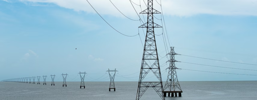
Contamination can originate from many different sources. Some obvious contributors of contamination include salt spray and fog, heavy industry, airports and desert conditions.


Performing a pollution severity assessment is critical to understanding the Site Pollution Severity (S.P.S.), measuring equivalent salt deposit density (ESDD) and non-solid deposit density (NSDD) per IEC 60815.
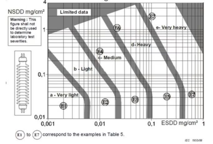
Fig. 1: This chart identifies the severity of site contamination. Source: IEC 60815.
After the assessment is completed, mitigation plans can be developed to ensure proper insulator performance.
Examples of contamination mitigation
There are many different options to manage site contamination:
- Short-term methods that remove contamination immediately, with high operational costs. These do nothing to further resolve the issue and are often repeated.
- Mid-term solutions that extend the frequency between required interventions also requiring significant capital to implement.
- Long-term solutions that resolve the issues of contamination for the life of the insulator.
Short-term methods for mitigating primarily focus on removal of the contamination by:
- Washing with de-ionized water
- Blasting with an abrasive medium such as walnut shells or crushed corn cobs
Mid-term methods of mitigation include:
- Field Coating with Room Temperature Vulcanized silicone
- Using High Temperature Vulcanized Composite insulators
- Installing shed extenders
- Increasing height and therefore the BIL of the insulators
- Following IEC 60815 recommendations of increasing the creepage distance of insulators
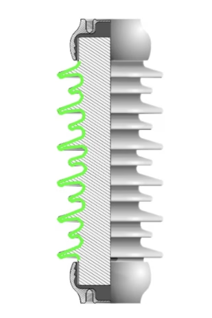
Fig. 2: The Creepage distance of the insulator as the shortest path from line to ground along the surface of the insulator, highlighted in green. Source: LAPP Insulators.
Mid-term solutions will often require further mitigation of contamination. Increasing BIL will cause insulation coordination issues and structure rating issues due to increased moments. Shed extenders prevent natural washing and can act as contamination traps that will cause glaze degradation due to increased localized leakage currents.
Long-term, permanent solutions to contamination are Resistive Graded (RG®) semiconductive glaze insulators.
How semiconductive glaze works
The theory behind semiconductive glaze is not new; it was originally patented by C.W. Marshall and J.S. Forest, British Patent No 525357 or Paul Horton of General Electric, US Patent US2797175A. Semiconductive glaze allows for a small amount of controlled current to flow through the ceramic insulator’s glaze.
This current produces several advantageous effects, primarily:
- A graded electric field
- A heating effect
- Dry band arc prevention
Grading the electric field
First, RG® glaze grades the electric field and voltage around and along the length of the insulator. This leads to a reduction in Corona and Radio Influence Voltage. There is not a tight e-field gradient at the line end (hot) of the insulator, which would cause corona and RIV to be produced from the hardware and cement joint interface.
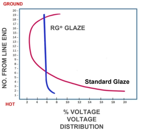
Fig. 3: A plot of a standard glaze insulator’s voltage gradient versus an RG® unit, assuming the line end (hot) is down, and the ground end (cold) is up like a transmission string. Source: LAPP Insulators.
Current = Heat
Second, a byproduct of electrical current is heat. When voltage is applied, the glaze warms up and maintains a temperature of about 4° Celsius above ambient air temperature.
This elevated temperature prevents condensation and ice from forming on insulator surfaces. The heating also helps dry an insulator quickly after a wetting, even reducing the time there is moisture on the unit and uncontrolled leakage currents.
Dry band arc prevention
Finally, the controlled current in the glaze prevents dry band arcs and eliminates flashovers from occurring. The conductive properties of the glaze complete the circuit linking leakage current paths. When contamination on the surface of the insulator becomes wet, it becomes conductive, and leakage currents flow through it. RG® glaze is conductive and completes the “circuits” that are independent leakage current paths. This completed circuit allows for an even voltage distribution and prevents the initiation of dry band arcs. On non-semiconductive glaze units, repeated dry band arcs ionize the air along the insulator, leading to a flashover.
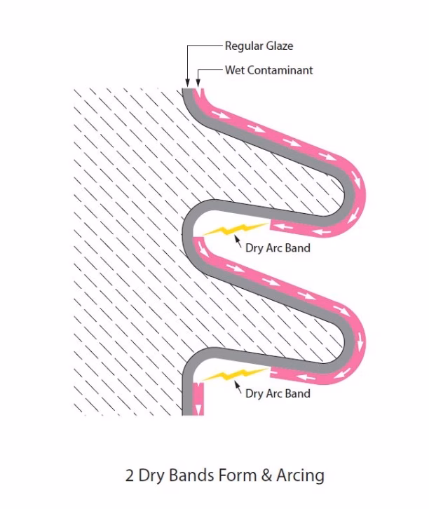
Fig. 4: A dry band arc forming between 2 leakage current paths. Source: LAPP Insulators.
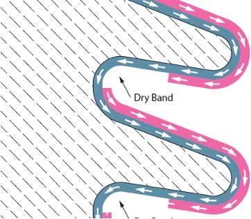
Fig. 5: A path for the current through the glaze, and no dry band arc. Source: LAPP Insulators.
Testing
Testing was performed at EGU per IEC 60507 clause 5 at multiple salinity levels to confirm insulator performance. Two different units were tested, a TR 286 high creepage (58mm/kV) standard glaze insulator and a TR 286 stand creepage (38mm/kV) resistive graded unit.
Results
The standard glaze high creepage unit (58mm/kV) passed salinity concentrations up to 160 kg/m3 with significant dry band discharge activity on the unit. The unit exhibited significant electrical activity.
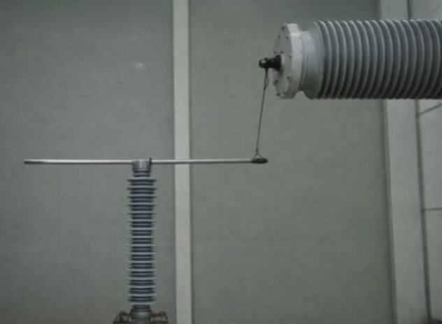
Fig. 6: The high creepage insulator set-up. Source: LAPP Insulators.
| Test No. | Test Voltage (kV) | Time (min) | Salinity (kg/m³) | Result |
| 1 | 71 | 60 | 160 | No flashover |
| 2 | 71 | 60 | 160 | No flashover |
| 3 | 71 | 60 | 160 | No flashover |
Table 1: Results from the EGU report for the standard glaze High Creepage unit. Source: LAPP Insulators.
The RG® standard creepage unit passed the 224kg/m3 salinity concentration, the highest concentration possible in room temperature water with no discharge activity. The heating of the glaze allowed for thick salt deposition on the surface, yet showed no electrical activity at all.
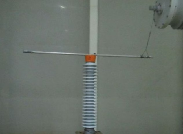
Fig. 7: The setup of the standard creepage RG® insulator. Source: LAPP Insulators.
Test No. | Test Voltage (kV) | Time (min) | Salinity (kg/m³) | Result |
| 1 | 71 | 60 | 224 | No flashover |
| 2 | 71 | 60 | 224 | No flashover |
| 3 | 71 | 60 | 224 | No flashover |
Table 2: Test results from the EGU report for RG® standard leak unit.
Conclusion
The RG® semiconductive glaze with standard creepage (38mm/kV) distance significantly outperformed the regular glaze high creepage distance (55mm/kV) unit. The RG® glaze withstands the most aggressive salinity testing set by IEC 60507, and the lack of any activity on the RG® unit proves that it is more stable in a contaminated environment.
RG® glaze is integral to the insulator, not a coating. It has 40+ years of proven in-service field experience, meaning it can be expected that it is an effective long-term solution, reducing the need for traditional contamination mitigation practices.
*The information provided in this content is for informational purposes only and should not be considered professional advice. We make no warranties or guarantees, express or implied, and are not responsible for any losses or damages resulting from your use of this information.