Find Content
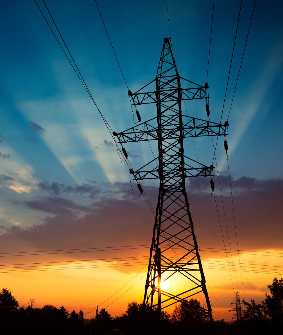
Increasing the Seismic Resilience of Porcelain Insulators in Electrical Substations
With the National Earthquake Information Centre locating approximately 55 earthquakes per day worldwide, ensuring seismic resilience is crucial to guarantee the consistent operation of the electrical grid.

Key Takeaways
Background
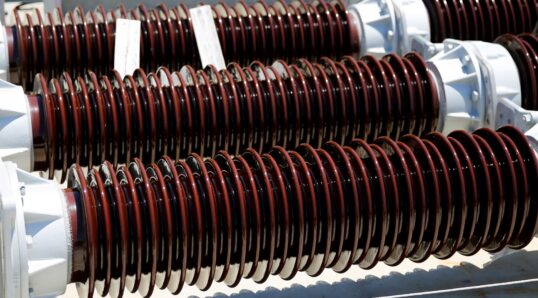
Insulators play an integral part in the operation of electrical substations. Porcelain’s rigid nature allows for minimal flex, making it an ideal material choice for substation insulators in areas of seismic activity, as maintaining consistent component alignment is critical in preserving substation safety and operational reliability during seismic events.
While porcelain insulators can be prone to damage from earthquakes, with the optimal design, material composition, and manufacturing processes, engineers can guarantee maximum performance against seismic impact, increasing the resilience of their substations.
Force
Similar to seismic events, high-voltage towers and equipment exhibit lower levels of Natural Frequency. When a seismic event occurs, resonance is produced by the matching frequencies, causing increased motion, which induces significant cantilever loads. Cantilever loads determine the core diameter, and thus the weight of the insulator.
Ceramic materials have high compression ratings and low-tension ratings. Earthquakes cause ‘bending moments’, resulting in compression and tension stress.
Weight
Tensile stress is amplified by the lever action of the height of the insulator, meaning bending moments increase with greater force and/or taller insulators.
In calculating the force/energy that strikes during a seismic event, weight is a key factor. Optimising the design to maximise the strength-to-weight ratio is the key to increasing seismic resilience.
Insulator weight reduction can be achieved in several ways:
- Insulator strength can be enhanced by using software to optimise insulator design and by maintaining quality assurance during manufacture.
- Reducing shed size.
Optimised Design
Often, insulators used in substations are based on standard general-purpose designs. When considering insulator design for substations in areas prone to seismic activity, a more bespoke approach is necessary.
Digital software should be used to evaluate the entire assembled and mounting structure of the insulator. This will identify high-stress areas and low-stress zones for a given configuration.
The equipment designer/consultant should then work closely with the insulator manufacturer to ensure all zones have an equal safety margin. It can take several iterations to fully identify all optimum increases and decreases in strength at given locations throughout the insulator.
Identifying and remedying lower stress areas reduces weight in that area. As a result, top-section weight reductions decrease the strength needs in lower sections. This leads to less mass, less motion caused by the mass, and less overall stress.
Insulator Positioning
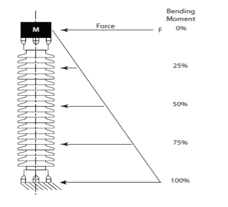
The location of an insulator in the equipment is fundamentally important. In many cases, insulators are used to support a heavy piece of equipment. If the equipment is compact with the mass near the top as in Fig. 1, very little bending stress occurs on the top fitting.
If the equipment has a high centre of gravity with the mass well above the insulator, the top fitting will be subjected to a much greater bending stress. In these cases, a more robust design of the top portion is called for. In Fig. 2, the top of the insulator is subjected to 50% of the maximum bending loads.
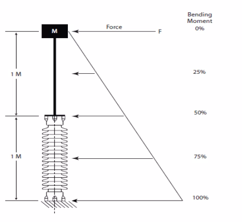
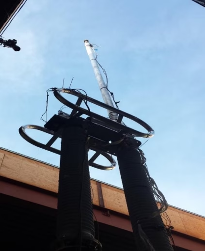
Mass at the top of the insulator has the greatest bending effect. In the case of an air break switch in the open position with the mast fully extended, high bending moments are found at the top of the insulator.
Reducing Sections
Insulators are comprised of single or multiple sections bolted together. High-voltage insulators can contain many sections, depending on the voltage level. Stress concentrations occur at the joints where the cast iron fittings are cemented onto the porcelain. The diameter of the porcelain at the fitting is increased due to the concentrated stress levels. Reducing the number of sections will reduce high-stress locations and the weight of any additional fittings.
Where multi-stack insulators are used, the optimal maximum section length should be determined and enforced.
Shed Size
Shed profiles are commonly used to increase creepage distance, but as sheds add weight to the insulator, this must be a consideration when designing an insulator in areas sensitive to seismic shifts.
In the past, sheds have typically been up to 19mm at the core, tapering down to 12mm at the tip. With recent improvements in material science, this shed size can now be reduced by up to 20%, thus reducing the overall insulator weight.
Material Optimisation
Porcelain insulators contain a mix of Kaolin, Alumina, Feldspar and Silica (Quartz). Under IEC 60672-3, there are 3 main insulator types – C-110, C-120 and C-130.
C-130 normally has alumina content >30%, which increases the strength and thus obtains the highest strength-to-weight ratio. Insulators manufactured with C-130 clay can reduce weight by up to 40%, making them an ideal choice in seismically active regions.
Manufacturing Processes
Insulators are manufactured by a process called Wet or plastic methods. To obtain consistent body strength, all steps leading up to a finished product must be consistent.
Isostatic production is a much more consistent process that requires less drying time than wet clay or plastic methods, which involve a lot of manual inspection and take 3 times longer to dry.
With isostatic production, the turning step is performed dry, eliminating the shrinkage from wet-turned profiles to the dry/ready-for-firing state. This results in tighter tolerances.
Conclusion
Improving the seismic performance of porcelain insulators is possible by reducing insulator weight, which can be achieved by optimising the insulator design based on actual needs and using high-strength materials with consistent manufacturing processes.
References
[1] IEEE 693-IEEE Recommended Practice for Seismic Design of Substations-2005
[2] IEC 60672-3, Specification for Ceramic and Glass insulating materials, First edition 1984
[3] IEC 60273, Characteristics of indoor and outdoor post insulators for systems with nominal voltages greater than 1000V, Third edition 1990
[4] T Johansson, G Gödel, P Maloney, “Optimized Insulators for Different Environments and Applications
*The information provided in this content is for informational purposes only and should not be considered professional advice. We make no warranties or guarantees, express or implied, and are not responsible for any losses or damages resulting from your use of this information.