Find Content
Porcelain Insulators Under Cycle Loading
Exploring the effects of repeated loading of solid core porcelain insulators.


Key Takeaways
Abstract
This paper’s objective is to explore the effect of repeated loading of solid core porcelain insulators. Typical ANSI and IEC mechanical testing differs greatly from real world loading characteristics that insulators experience in the field. Lab testing consists of relatively slow load over a 90 sec window, whereas field loading is generally cyclic or static loads.
Solid core porcelain insulators are comprised of several components: porcelain body, cast iron end fittings, and the Portland cement grout used in the assembly of the metal parts to the porcelain. Each component has a different reaction to loading.
Introduction
Porcelain insulators have been used in the global electrical system for over 120 years. The insulator designs have changed as the voltage requirements have increased. With increased voltage, insulators have become proportionately greater in height. Early station post insulators were comprised of a top threaded cap and a bottom pin with a flange. These insulators were stackable. This design was vulnerable to bending loads due to the fragile porcelain being outside the steel pin. The solid core station post, comprised of externally attached cast caps, was introduced in the 1960s.
Designing for Bending Loads
Station post insulators are subjected to many types of forces depending on the application.
These forces include:
- Cantilever or Bending
- Compression
- Tension
- Torsion
Understanding the types and levels of loads is the key to assessing the fitness of an insulator.
There are four common loads:
- Cantilever/ Bending
- Torsion
- Compression
- Tension
Of these, the Cantilever/Bending loads are the most critical.
Typical yield data exceeds the ANSI and IEC ratings for Tension, Compression and Torsion loads. This is not necessarily true for Cantilever/Bending loads, largely due to the nature of the material and how the load is applied. Porcelain has very high compression and shear strength vs. tensile strength.
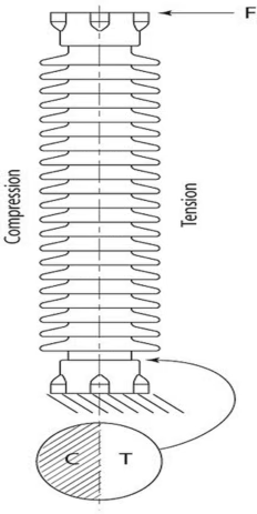
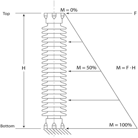
Bending moments induce Compression and Tension stress. Tensile stress is amplified by the lever action of the height of the insulator.
Bending Moments increase with greater force and/or length of insulators.
Design considerations
Cantilever ratings determine the core diameter of the porcelain.
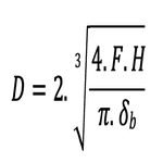
Where:
D – core diameter
F – Required strength (min. breakage load)
H – Height
𝛿𝑏 − Specific bending strength of porcelain
But the porcelain is not the only design criterion to ensure cantilever ratings are met. The fitting and how it’s attached also play an important role.
Insulator manufacturers typically have a range of stock fittings with incremental steps of increased strength. Increasing the fitting strength is achieved by:
- Diameter, limited by Bolt Circle Diameter (BCD)
- Casting thickness
- Overall height of engagement with porcelain
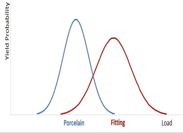
To limit the number of fitting options one might stock, a manufacturer might stock 5 sizes of any given BCD. The strength rating difference can be large between one to the next stronger size. A designer must select a fitting that exceeds the porcelain strength by enough margin to account for cyclic loads. In typical robust designs, most insulators will have porcelain yields as the mode of destruction.
Field loading vs. test methods
Users want to know if an insulator has been degraded after an extreme loading event or after being in service for many years.
Loads below 50% or loads greater than 100% of rating are clear. Loads up to 50% of rating are within the working loads and should perform in an elastic nature, without deterioration. Loads well above the rating can result in permanent damage or yielding.
ANSI C29.9 and IEC 60168 have strictly defined loading rates for Type, Conformance, and Routine tests. The ANSI and IEC standards specify loading rates and how they are to be applied. The first 75% of rating is to be applied quickly and smoothly; the remaining 25% of rating must be applied over a 60 to 90 second time frame, which can be summarized as a slow applied load. The cantilever rating is defined as the minimum yield level.
In the field, most loads fall into two categories- static loads or sudden cyclical loads. Static loads are seen where equipment is mounted horizontally.
Examples of cyclical loads include:
- Short Circuit loads caused by electromechanically induced attraction
- Seismic events where the resonance frequency closely aligns with the natural frequency of the overall equipment
- Loads generated from disconnect switch operations
Loads induced by Seismic activity on large high voltage insulators are of greater concern due to the ratio of mass to bending strength.
Understandably, some field loads are very difficult to simulate. Unlike test loads of one applied load, field loads occur over many years.
Effects of field forces on porcelain insulators
Substation designers will account for all reasonable combinations of loads while the equipment is in service. Each region has environmental load conditions that guide safety factors for each type of force. It is reasonable to expect that a designer would not calculate every possible load all in one event, although combination loading of two or more load types is common; for example, wind and ice. Calculated loads will fall within the working load of an insulator, commonly 40 – 50% of yield rating.
On occasion, the “perfect storm” occurs, when complex events cause loads above reasonable expectations.
Loads well above the insulator cantilever rating will most likely cause the insulator to yield instantly.
For loads above the ratings, the common yield zone is designed to be at the bottom of the porcelain, above the bottom fitting. The location is intentional for control. Loads above the working loads but below the rating are the point of interest.
Porcelain insulators utilize metal cast fittings which are attached by a Portland cement grout. The fitting is external to the porcelain, where the porcelain surface has texture to enhance bonding.
The strength of the grout joint bonding the cast fitting to the porcelain can degrade over repeated loading. To ensure predictability the hardware, fitting design and grout assembly are designed to exceed the porcelain strength. When fitting and bond strengths are lower than that of the porcelain, it is common that the porcelain will not break, but be pulled out of the fitting. The cement joints can begin to break down under cyclic loading if the load is near the expected yield level and the fitting bond strength is equal to or lower than the porcelain’s strength.
Some loads and their subsequent effects on an insulator are more difficult to predict.
Loads that are above the working load but below the expected yield level are not covered in the ANSI or IEC standards. The porcelain in this load range should remain elastic. This may not be the case for the fitting region.
Laboratory testing
To better understand the effects of loading outside industry standards and more aligned with extreme field loads, a test program was initiated to subject porcelain insulators to cyclic loads. The goal was to test at loads well above working levels, near the expected yield level.
Samples were designed to have the fitting and bond strength close to or equal in strength to the strength of the porcelain. The bell curves of each components predicted yield closely overlap.
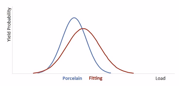
This approach was utilized to better understand the relationship between porcelain and the fixed hardware when subjected to cyclic bending loads.
The expected yield level is only an approximation.
SML, Specified Mechanical Load is:
SML = 𝑥̄ – 2σ
Where:
σ – Standard Deviation
𝑥̄ – Average Yield
To study the bending strength of a group of insulators, one must establish a statistical yield level for the lot. To have a more accurate prediction, 10 samples were tested to yield level. The data provided the average yield and the Std Dev. This was a key step, allowing loads to be selected for further testing safely below yield levels.
The challenge was to determine the bending test load levels that would not require thousands of load cycles to yield or cause yield within the first few cycles.
Test results
The ten samples generated an average Cantilever yield of 27.15 kN, 𝑥̄. The Std Dev was calculated at 2.49 kN.
The first tests were done to establish loads that would provide yields in less than 100 cycles. Two samples were tested in each iteration until a load level was reached with the desired results.
First iteration
Tests at 𝑥̄ – 3σ, 19.68 kN
Sample 1: 95 cycles to yield
Sample 2: No break in 100 cycles
It was decided to increase the bending loads from 𝑥̄ – 3σ, 19.68 kN to 𝑥̄ – 2σ, 22.17 kN. There was a concern that as the load was increased, samples could yield on the first cycle. This can be seen on a bell curve
at 𝑥̄ – 2σ, where 2.5 % could yield as the first load is applied.
Second iteration
Tests at 𝑥̄ – 2σ, 22.17 kN
Sample 1: No break in 100 cycles
Sample 2: No break in 100 cycles
With no yields in 100 cycles, the load was increased again. The load was increased from
𝑥̄ – 2σ, 22.17 kN to 𝑥̄ – σ, 24.46 kN
Third iteration
Tests at 𝑥̄ – σ, 24.46 kN
Sample 1: 38 cycles to yield
Sample 2: 172 cycles to yield
Six samples were tested altogether; five samples yielded during the 100 cycle tests. The sample that did not yield in the 100-cycle program was cycled until it yielded. The lowest value was recorded at 13 load cycles and the highest at 172 cycles. Because the 100-cycle loading was merely an arbitrary expectation for the test duration, it was decided to include all the data.
| Sample | Load, kN | No. of cycles |
| 1 | 24.46 | 38 |
| 2 | 24.46 | 172 |
| 3 | 24.46 | 39 |
| 4 | 24.46 | 13 |
| 5 | 24.46 | 52 |
| 6 | 24.46 | 29 |
Data from the testing of six samples. Std Dev 52.6859142, Average 57.1666667. Source: PPC Insulators.
Mode of yields
A digital camera was zoomed and focused on the cement joint due to the concern for personnel safety in the test hall. This allowed monitoring of movement of the porcelain with relationship to the cast fitting. A gap was observed of approx. 2mm between the cement and the fitting prior to the yield. Two distinct break patterns were noted: porcelain yielding at approx. 20mm below the top of the fitting, and porcelain pulling out of the fitting.

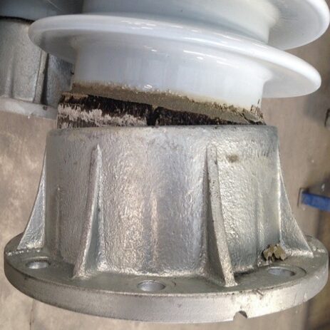
In the case where the porcelain break was 20mm below the top of the fitting, the cement bond was lost in the upper regions of the fitting, whereas when the porcelain pulled out, the cement bond was lost deeper in the fitting.
Conclusions
The study focused on insulators purposely designed to have the cast fitting bond as a weak link.
The ten insulators tested per ANSI and IEC Bending test standards to determine the starting loads resulted in a Std Dev of approx. 9% of the average lot yield, 2.49 kN vs. 27.15 kN.
When the Insulators were subjected to cyclic Bending loads to yield, they showed a large standard deviation with regards to measured number of cycles. The Std Dev and the Average were nearly equal, 52.7 vs. 57.2 respectively, approx. 92%.
Even though the insulators were of the same design and the same production lot, the performance under simulated extreme field loads showed much lower predictability.
The fitting bond strength was degraded by the repeated loads, reducing the bond surface area until yield.
Insulators are utilized in applications where cycle loads are likely, such as high mass and tall equipment. The fitting strength should be designed to ensure elastic behavior throughout the insulator.
*The information provided in this content is for informational purposes only and should not be considered professional advice. We make no warranties or guarantees, express or implied, and are not responsible for any losses or damages resulting from your use of this information.